Difficulty
Moderate
Steps
47
Time Required
02:00:00 - 03:00:00
- 01 - Frame Assembly 5 steps
- 02 - A/B Drive Assembly 5 steps
- 03 - X/Y Joint Assembly 7 steps
- 04 - X Carriage Assembly 7 steps
- 05 - Gantry Assembly 4 steps
- 06 - Front Idlers/Tensioners Assembly 3 steps
- 07 - Run the Belts 8 steps
- 08 - Assemble A/B Motors 4 steps
- V1 - 9. Assemble Bed 4 steps

User-Contributed Guide
This guide is not managed by the site's staff.

In Progress
This guide is currently being written. Reload periodically to see the latest changes.
-
-
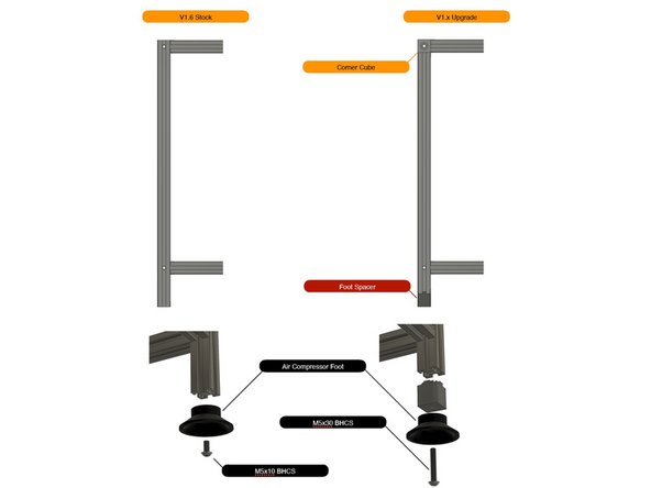
Make note of the vertical extrusions if you are upgrading or doing a new build.
-
-
-
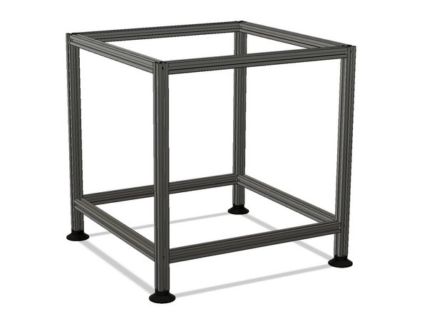
Build your frame on a flat surface to help square your frame. Granite countertops work well. Other tools such as a machinist square will work well too.
-
Loctite is not required on the joints but can be added for extra peace of mind.
-
-
-
Include the extra spacers if you are upgrading from an early V1 build.
-
-
-
Check that your completed frame is square.
-
Frame should not rock or wobble on a flat surface.
-
Measure diagonals and remove any variance as much as possible.
-
-
-
It's easiest to run a flat down the length of the entire 5mm shaft.
-
The flat only needs to be deep enough for the grub screw to catch and not slip.
-
When your pulleys are in place, be sure to loctite your grub screws.
-
-
-
Add the drive stacks to the printed pieces along with another 20t pulley to lock the stack into place.
-
-
-
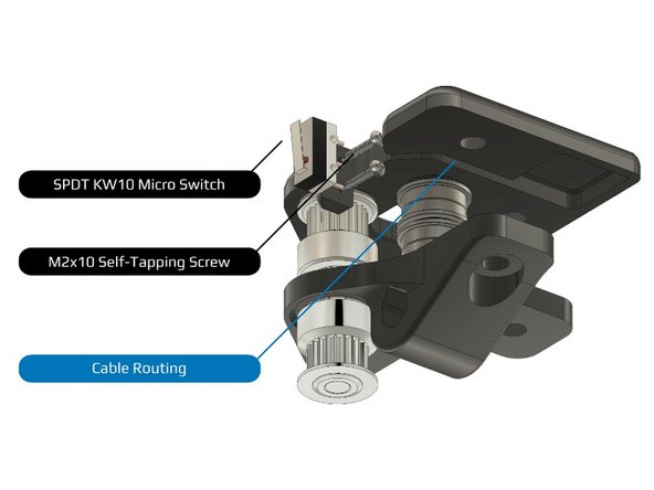
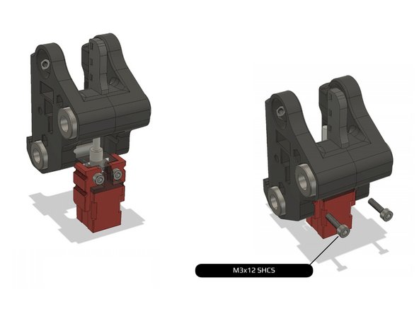
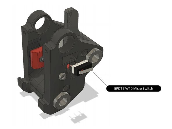
Be sure to wire the micro switch as NC (Normally Closed). On most switches this means connecting wires to the outer two terminals on the switch, but you can check with a multimeter by making sure there is continuity at those pins when the switch is not pressed.
-
Add a vertical line to the 20t pulleys in each stack so you can troubleshoot slipping grub screws easily.
-
-
-
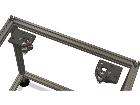
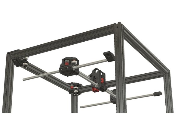
The assembly with the micro switch attaches to the right side of the frame.
-
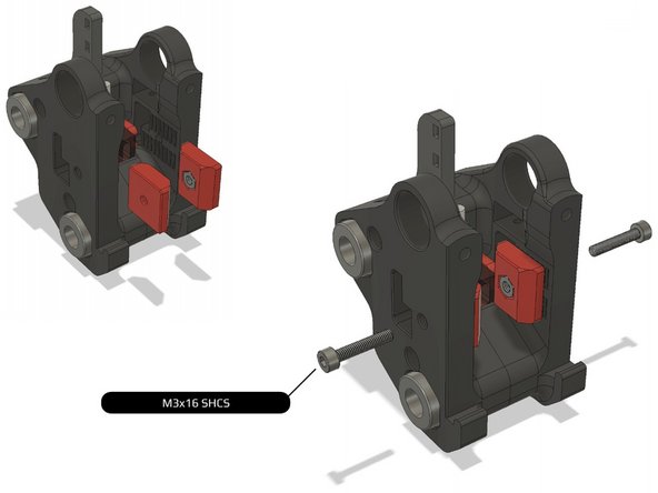
Be sure to run wiring through the channel and be careful to not damage it while tightening.
-
-
-
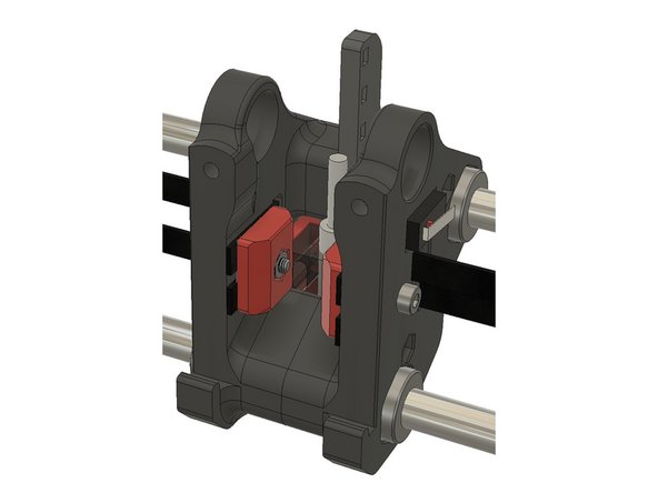
Ensure the two halves mate cleanly or you can have twist along the X axis.
-
Clean up parts with a hobby knife or small file if necessary.
-
-
-
Insert wisdom here.
-
-
-
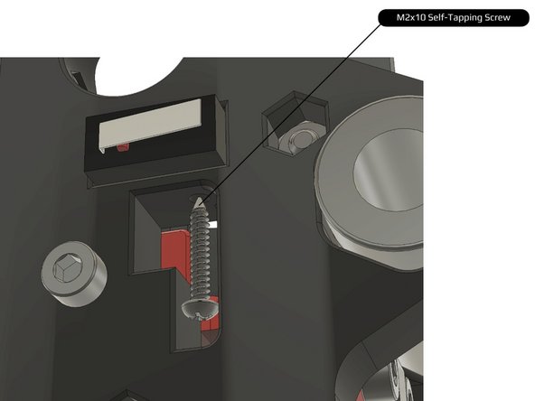
Be careful not to over-tighten screws into plastic.
-
-
-
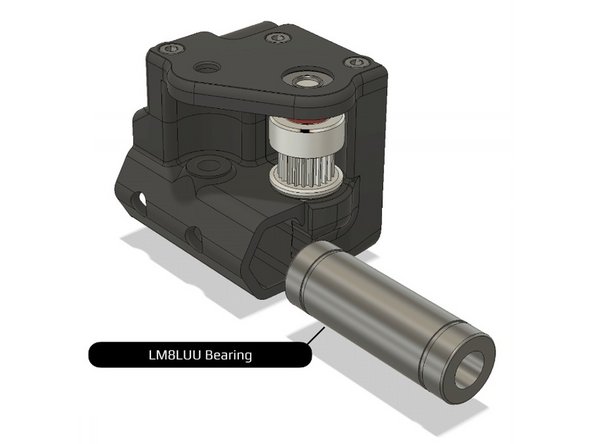
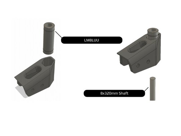
LM8LUU bearing should fit snugly.
-
You can use a c-clamp or similar tool to apply a slow and steady force to slide the bearing in if necessary.
-
-
-
Insert wisdom here.
-
-
-
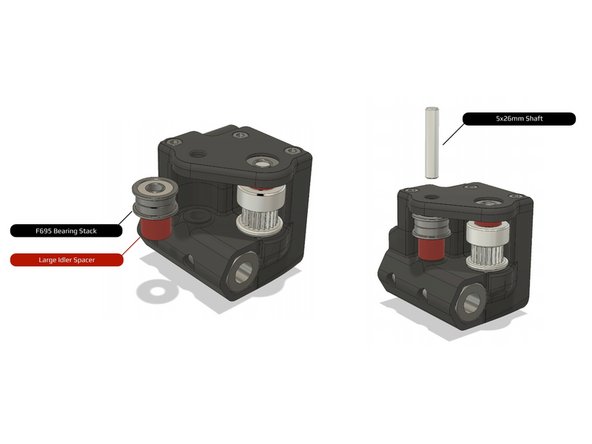
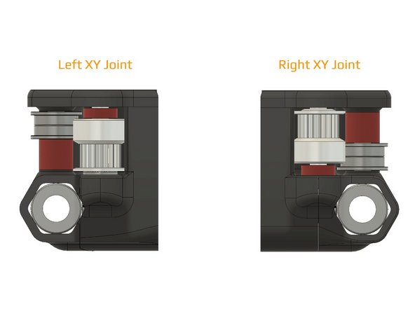
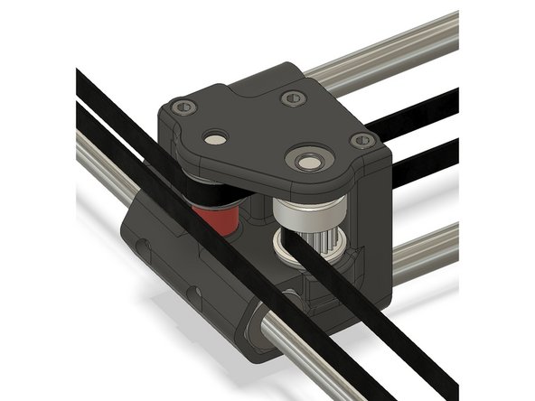
Double check that your spacers and pulleys are located and oriented correctly.
-
-
-
Be careful not to crack the carriage pieces when inserting the bearings.
-
-
-
The M3 nuts for securing the toolhead can fall out. They can be added later if necessary. Or secure them in place with a short spare M3 bolt temporarily.
-
-
-
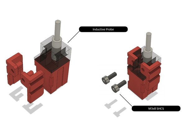
If the probe tabs did not print cleanly, you may need to substitute M2 hardware, clean up the part with a hobby knife, or reprint the pieces.
-
-
-
Insert wisdom here.
-
-
-
Insert wisdom here.
-
-
-
Be sure to wire switch in the NC position.
-
-
-
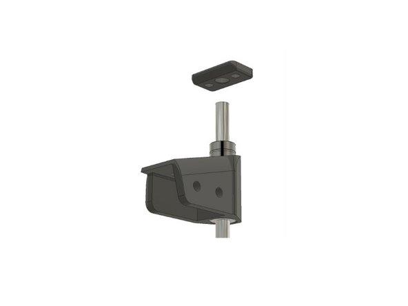
Be sure to lube the bearings before adding the 8mm rods.
-
-
-
Be sure to add lube to the bearings before assembly.
-
-
-
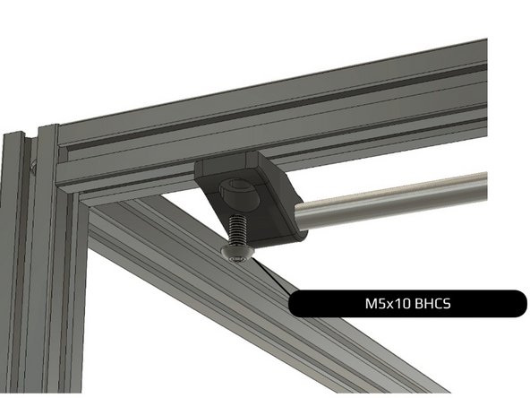
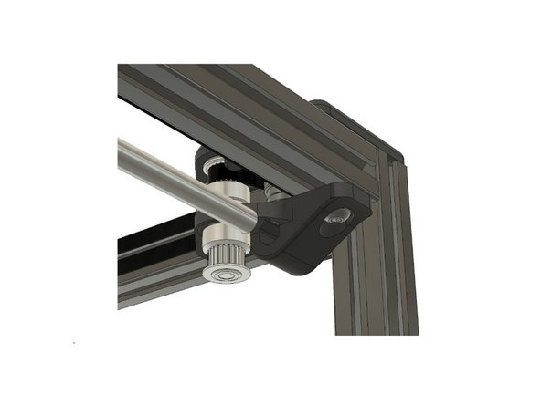
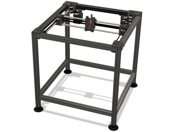
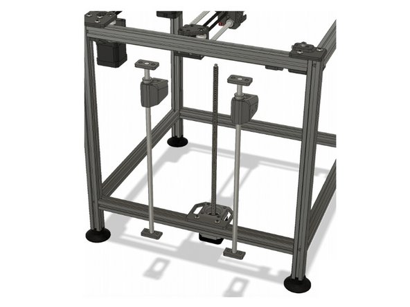
Ensure smooth movement on both axis before tightening down to the frame.
-
-
-
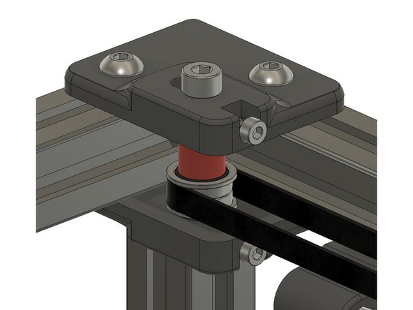
Wait until you run your belts before tightening the tensioners.
-
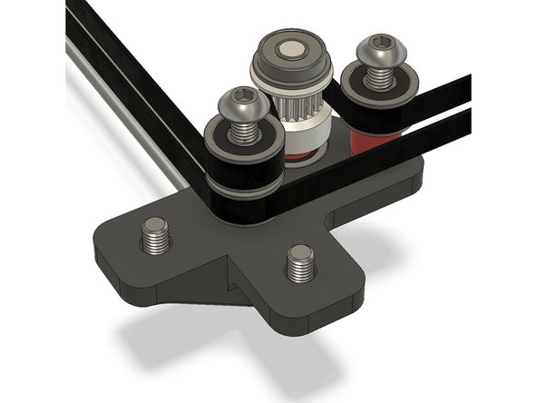
Do not overtighten the M5 bolts. The F695 bearings should spin freely.
-
-
-
Insert wisdom here.
-
-
-
Study the belt path.
-
Best practice is to run one belt before cutting. Use this belt to measure the other belt to the exact same length (by tooth count). Leave at least 1 inch (2-3cm) spare on one side so you can tighten by hand easily.
-
-
-
Start at the carriage. Set the belt flush to the edge and tighten the belt retainer.
-
-
-
Run the belts to the X/Y joints. The toothed side should run against the 20t pulleys. The smooth side should run against the flanged bearings.
-
-
-
Run one belt to the front idler/tensioner and back to the X/Y joint.
-
-
-
Continue running both belts to the rear.
-
One belt will engage the drive pulley.
-
Run both belts across the rear of the frame.
-
Run the other belt through the drive gear on the other corner.
-
Use paper clips or zip ties to help force the belt along the correct path as necessary.
-
-
-
Run the belts down the other side through the X/Y joint and front idler.
-
-
-
Finish the run at the carriage.
-
Double check that your belts both follow the correct path.
-
Ensure tensioners on both sides are completely loose.
-
If you cut both belts to the exact same length, pull both of them tight and ensure the same length extend beyond the X carriage.
-
Tuck spare belt back into the carriage.
-
-
-
If you opt out of using dampeners, you may need to adjust or rotate the 20t pulley.
-
-
-
Do not over-tension the 110mm belt loop.
-
Apply loctite to the grub screws.
-
-
-
Double-check your assembly.
-
-
-
Insert wisdom here.
-
-
-
Distance shown is from the front of the printer.
-
Use calipers to measure placement.
-
-
-
Insert wisdom here.
-
-
-
Use calipers to measure placement.
-