
Difficulty
Moderate
Steps
9
Time Required
- Voron Pocketwatch Assembly Guide 9 steps

User-Contributed Guide
This guide is not managed by the site's staff.
Quiz
0
Introduction
The Voron Pocketwatch filament feeder, aka extruder, is a small lightweight Bowden tube based mechanism for use in tight spaces, such as the Voron 0 3D printer. This extruder is simple in design, and easy to assemble, using industry standard components, along with 3D printed parts.
The compact design of the Pocketwatch makes it easy to adapt to many different 3D printers. The extruder is mounted with only two screws, so simple adapters can be created to install on most any 3D printer.
A Pocketwatch fits anywhere!
Tools
-
-
In following this guide, it is best to, first, read the whole guide, and second, as you build look ahead a couple of steps to make sure you understand how what you are doing now relates to what you are going to do later.
-
In this step, before you affix anything, "dry" fit these parts with those in the next few steps. IMPORTANT: Be careful with the bearings, you may not be able get them back off the shaft, if you put them on now, so just eyeball the fit.
-
Install the drive gear onto the motor in the orientation shown, positioning the gear correctly for mating with the large white BMG gear. Snug the set screw. You will tighten it fully later.
-
With the large white BMG gear, you are making a stack of bearings and driven gears.
-
Note: Depending on where you sourced the white gear, actual BMG, or clone, the tolerances and fit may differ from the illustrations.
-
Again, just snug the set screw. You will apply the thread locking compound in a subsequent step.
-
-
-
Take the motor attachment half of the extruder housing (body) and attach the motor. Note the different sized screws.
-
-
-
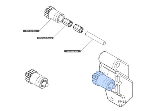
In this step you will lube and assemble the BMG idler gear with internal needle roller bearings.
-
The BMG gear kits usually come with two shafts. Check each against the printed part. One will be a good fit. The shaft ends must not be proud of the plastic guidler door when assembled.
-
Grease the bearings with a small amount of white lithium grease. Assemble the bearings, shaft, and idler gear, and press into the guidler, noting the correct orientation of the gear.
-
Check that the shaft is fully seated in the plastic part, and the gear spins freely. Work the gear back and forth to distribute the newly applied grease.
-
-
-
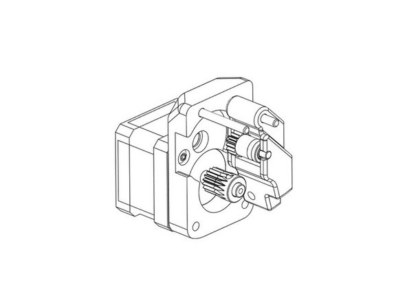
In this step, you will alignment the gears, and tighten the set screws that were just snugged previously.
-
Loosen and remove the the set screws. Apply a small amount of thread locking compound to the set screws, and re-install.
-
After aligning all the gears, slide on the guidler onto the extruder body, as shown. Check the alignment of the filament path with a piece of filament to ensure it will be driven through the extruder smoothly. Adjust as necessary.
-
Now, thoroughly tighten the set screws, and wipe off any excess compound.
-
Check that the whole mechanism is working smoothly. There will be resistance from the motor, but otherwise operation should be without any binding.
-
-
-
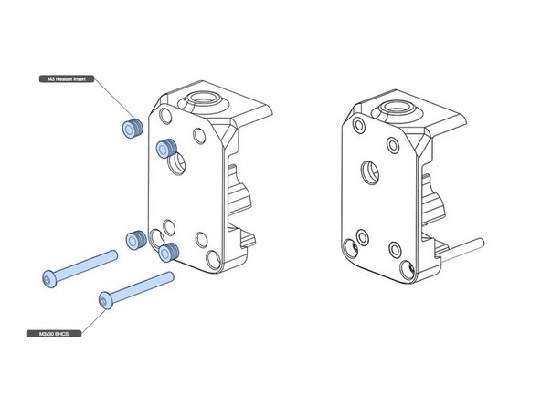
There are four heatset threaded inserts to be installed in the other half of the extruder housing
-
Using a soldering iron with a conical tip (or special heatset insert insertion tip), install the threaded inserts. Inserts should be flush, or a hair below the housing surface.
-
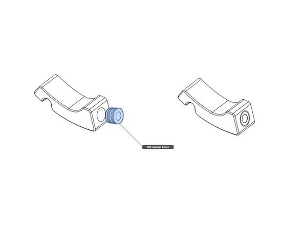
Do the same with the insert that goes into the shuttle, as shown.
-
Install the two long screws in the housing half.
-
-
-
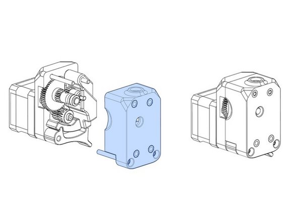
Before assembling the body halves, check that the filament path passes filament smoothly from hole to hole. Make adjustments, if necessary, with the right size drill bit, but do so as little as possible, so that the constrained operation of the filament path is maintained.
-
Assemble the two housing halves, as shown. Examine the illustration. Two screws will screw into the motor, and two will screw into two of the threaded inserts installed in the previous step.
-
The remaining two threaded inserts are used as attachment points for the extruder to a printer. An adapter is required for your specific printer. If a Voron 0, the adapter is part of the printed parts set.
-
-
-
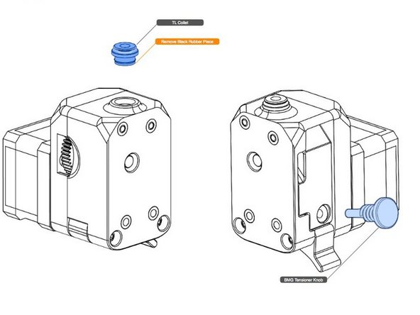
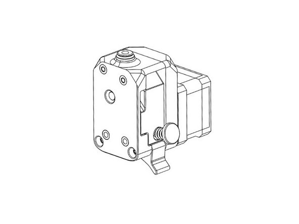
Install the Bowden collet, after removing the black rubber seal from the bottom, which is not used in this application. The collet is a press fit.
-
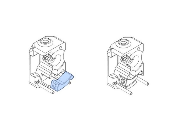
Screw the tension screw with spring into the receiving shuttle.
-
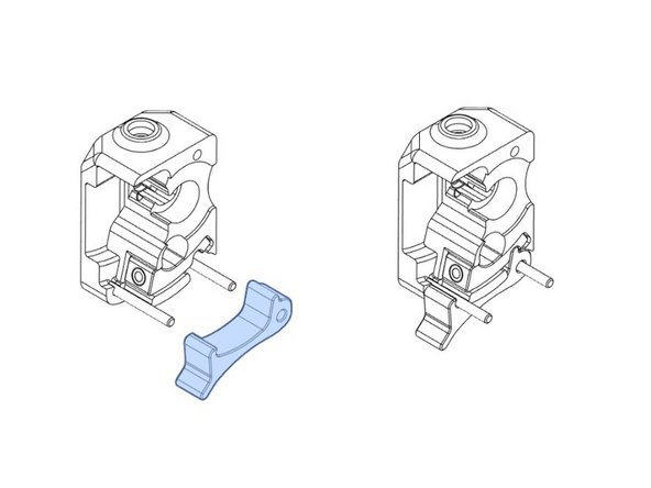
Close the latch and ensure that it works as expected.
-
-
-
Congratulations. Your Voron Pocketwatch is complete. As they say: Happy Printing!
-


Thanks to ArmyAg08 for review duty.
Thanks to ArmyAg08 for review duty.
Cancel: I did not complete this guide.
4 other people completed this guide.