
Difficulty
Moderate
Steps
5
Time Required

User-Contributed Guide
This guide is not managed by the site's staff.
Quiz
0
-
-
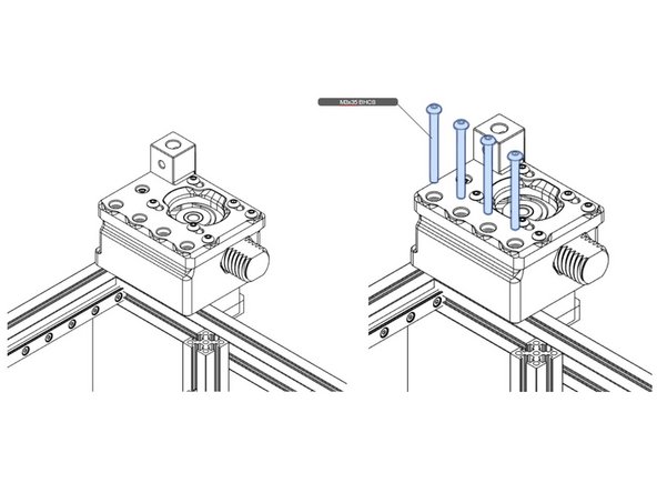
This step shows the assembly of the left drive unit. The right drive unit is assembled similarly with the bearing stacks flipped.
-
The screws in the first illustration are used as mounting shafts for the pulleys.
-
Take careful note of the bearing stack order with associated washers.
-
Check that the 9mm printed spacer is indeed 9mm. If not, re-print it.
-
In the last illustration, M3 nuts are pressed by hand into the printed part. If the press is difficult, you can use parallel jaw pliers to assist, but be careful, and check for stress marks in the plastic. If these marks are severe, you will have to re-print the part.
-
-
-
Note pulley orientation for the left B unit. The right A unit will be flipped.
-
Thread locking compound is used on the pulley set screws. Align the pulley, first, with the corresponding pulley stack. Lightly snug one set screw. Apply locking compound to the other screw and secure tightly, then remove previous screw and tighten it up similarly with compound.
-
Secure the motor with indicated screws.
-
-
-
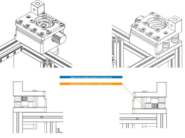
After having assembled both drive units, attach them to the frame, as shown. This is one of the times when you will discover whether you followed all the pre-insertion nut instructions in previous parts of the guide.
-
Read the next step before attaching the drive units to make sure the bearing stacks are correctly installed.
-
-
-
Using the diagram, check that the bearing stacks are oriented correctly. Backtrack and correct, if necessary, before proceeding.
-


Cancel: I did not complete this guide.
2 other people completed this guide.