
Difficulty
Moderate
Steps
14
Time Required

User-Contributed Guide
This guide is not managed by the site's staff.
Quiz
0
Tools
Parts
No parts specified.
-
-
For the steps in this alignment section, you are going to need a stable, flat, level surface on which to test alignment, and make adjustments.
-
Tools, such as levels and squares, will make precision easier.
-
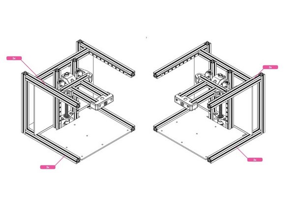
To start, loosen the screws on all the beams indicated in the illustration, but not so loose that the frame comes apart.
-
-
-
Check that the top and bottom beams are parallel to each other. Make adjustments and tighten the appropriate screws.
-
-
-
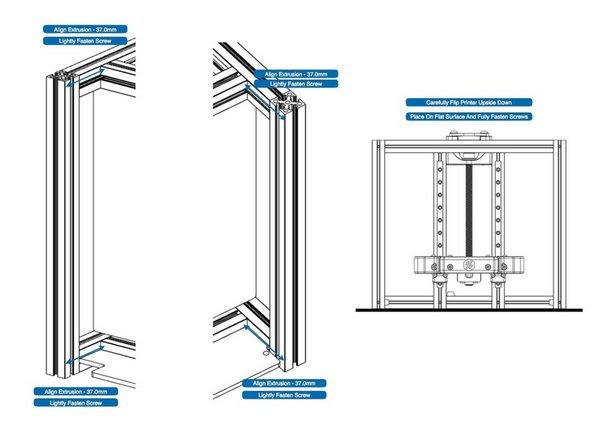
Check and adjust the horizontal beams that support the Z assembly to an offset distance of 37mm.
-
Do not fully tighten the screws.
-
Flip the frame over, carefully, staying on the flat surface, and finish tightening the screws.
-
-
-
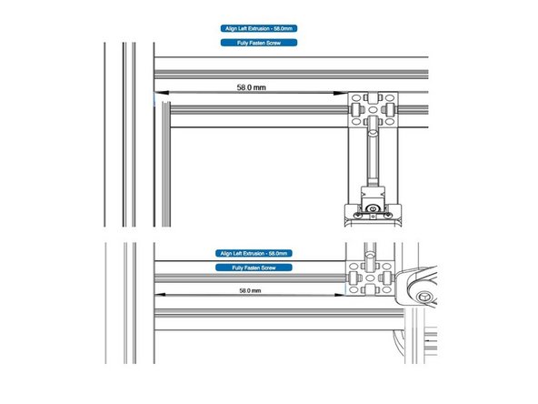
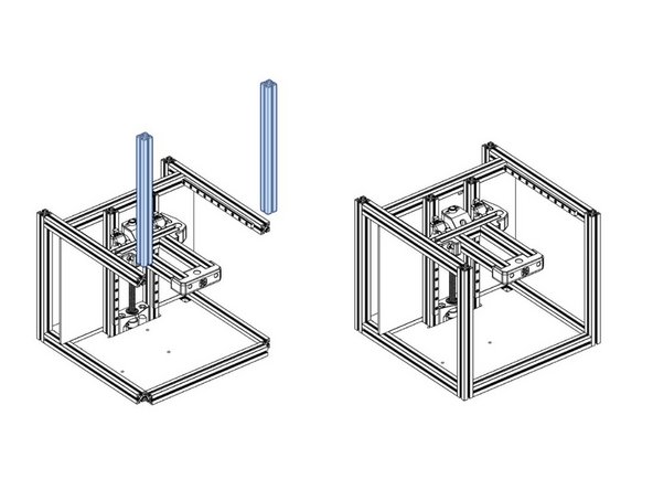
Adjust the Z verticals to 58mm on the left side, at top and bottom, and tighten the screws. This will center the Z assembly as seen in the second illustration.
-
-
-
Turn the frame back upright.
-
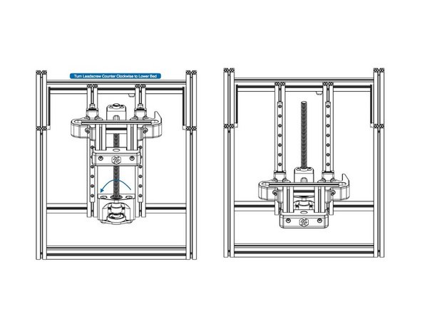
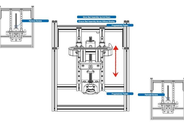
Turning the lead screw counter-clockwise, lowers the bed.
-
If you opted for a POM nut (made of polyoxymethylene material) instead of a brass nut then, you will feel moderate resistance when turning the screw. This is normal and is because of the tighter tolerance of the POM nut.
-
-
-
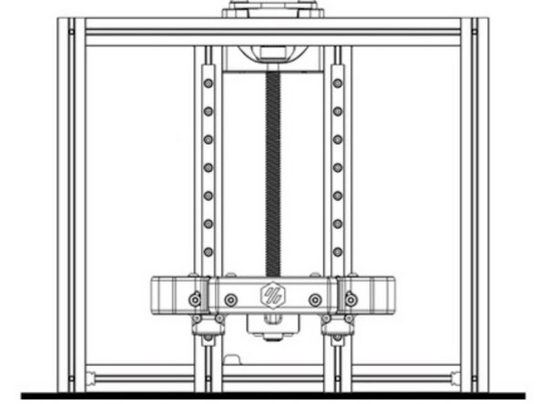
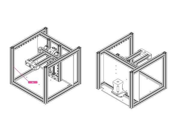
With the bed carrier lowered , remove the two screws securing the lead screw nut.
-
Move the bed carrier up and down, holding it in the center. Ensure there is no binding in the motion. It should be nice and smooth. Gradually tighten the vertical rail beams at the top, check motion continuously.
-
When both beams are tight, do a final check for smooth operation.
-
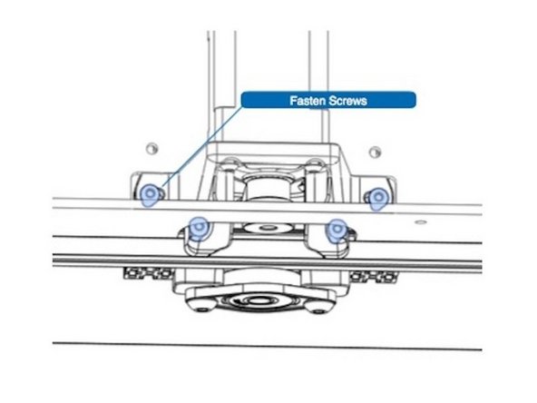
Re-install the lead screw nut screws and tighten.
-
-
-
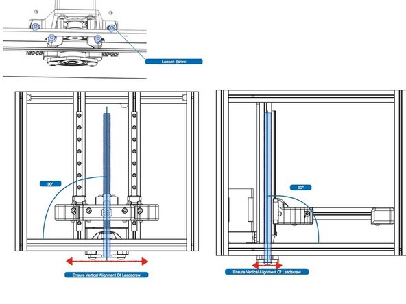
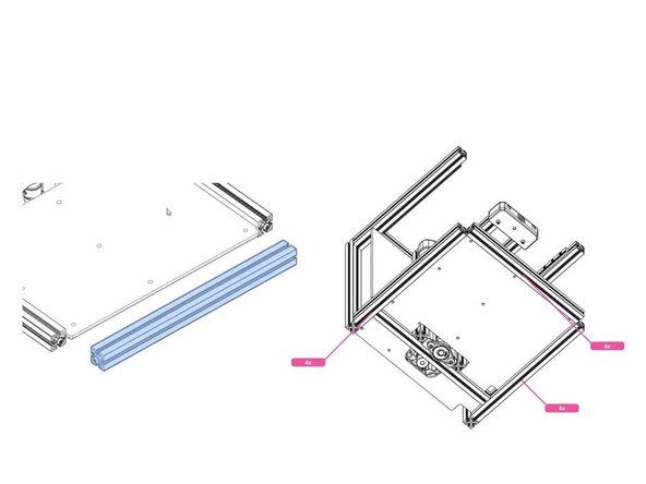
Loosen the four screws indicated to allow for adjustments to the lead screw position.
-
With a square, or other measuring device, position the lead screw at 90 degrees with respect to the bottom beam.
-
From the side of the frame, adjust lead screw at 90 degrees to the side bottom beam.
-
Tighten the screws half way. Re-check 90 degree angles.
-
Fully tighten screws. Re-check alignment.
-
If you're having trouble with this step, be sure the leadscrew is correctly aligned. Turn the leadscrew with your fingers. If you feel the resistance changing as the bed moves up/down, that is a sign the leadscrew is not at 90 degrees. You should be able to move the bed fully up and down with thumb and fingertips, only, turning the leadscrew.
-
-
-
First slide in one M3 nut as shown.
-
Slide deck panel into the extrusion slots.
-
-
-
First, add M3 nuts as shown.
-
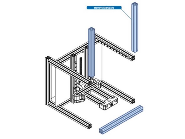
Re-install the front bottom extrusion, slotting the deck panel into it.
-
Tighten screws.
-
-
-
Slide the front vertical extrusions into place, and tighten the screws.
-
-
-
The frame alignment is now finished, but before moving onto the next section, add four more M3 nuts as shown.
-
Congratulations! Your printer's frame has been trued and squared, a very good start to the build.
-


Cancel: I did not complete this guide.
3 other people completed this guide.