
Difficulty
Moderate
Steps
11
Time Required

User-Contributed Guide
This guide is not managed by the site's staff.
Quiz
0
-
-
IMPORTANT: If you bought a Kee Pang lead screw, DO NOT USE IT! This lead screw has been seen to create banding artifacts in prints on multiple printers. Replacing it solved the problems.
-
Before assembling the lead screw assembly, check that all of the parts are clean, the screw rod has no burrs at its ends, or along the shaft, and the pulley teeth are not marred. Also check that the brass nut, used in a later step, moves smoothly on the screw rod.
-
The bearing in the pillow block should rotate in the block frame, similar to the action of a gimbal. If it does not move, use a dowel rod to break it loose, add some lubricant, and work it for smooth operation. Note, using the lead screw as a lever risks bending it, so a dowel rod is better, or the right size hex key, if you have one.
-
Check that the bearings move freely. Any perceived roughness in a bearing will amplify under load, so bearings cannot be good enough.
-
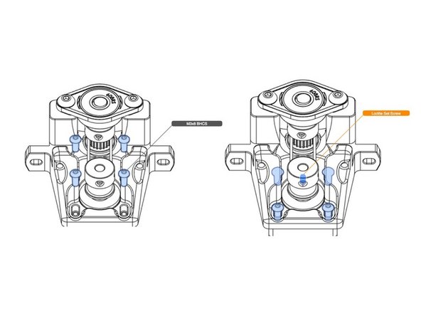
Assemble as shown in the illustration.
-
If desired, the printed spacer can be substituted with an equally dimensioned metal shim.
-
The pulley set screw should not be tightened until the next step. All other set screws should be tightened now.
-
IMPORTANT: In general, set screws are secured with medium strength thread locking compound throughout this manual, and is highly recommended.
-
-
-
Install the drive belt onto the pulley.
-
Insert the lead screw assembly into the motor mount, and seat the bearing into the mount. Push the pulley against the spacer/bearing.
-
Referring to the third illustration, make sure the set screw on the pillow block (in blue) is tight. Then push down on the leadscrew from the top. While pushing down on the leadscrew, push UP on the pulley/spacer/ bearing stack, making sure it properly seats into the plastic. Tighten the pulley set screws.
-
Check that the bearing is still fully seated in the mount, and the pillow block bearing is flat against the mount screw holes.
-
On the motor side of the motor mount insert the two M5 nuts, as shown. Secure the pillow block bearing with screws inserted on the other side as shown. Tighten to secure the whole assembly.
-
As final check, ensure that the lead screw operates smoothly and the bearing is properly seated in the plastic.
-
-
-
Holding the motor's drive pulley with the belt positioned on it, insert the motor through the mount and into the pulley.
-
With the four screws shown in the second illustration secure the motor in the mount, but do not fully tighten.
-
Align the motor's pulley with the lead screw pulley, and fully tighten the set screw.
-
Adjust the motor to put some tension on the belt, and tighten down the motor mounting screws.
-
-
-
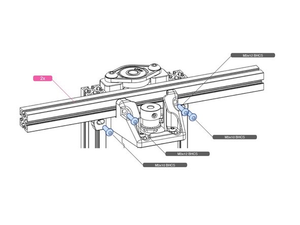
The lead screw nut is held in a bracket that attaches to the bed frame. As the lead screw turns, the bed travels with the nut.
-
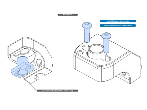
Install the nut into the bracket, as shown. The screws will screw into the nut's flange.
-
If your lead screw nut is not the "slim" type, as shown in the illustration, but is round, it can still be used after a little modification.
-
The nut needs to be flat on one side to fit into the bracket. File down one side, or use a rotary tool cutoff wheel, being careful not to damage the threads. Note that you need to cut it such that two holes will line up with the two screw holes in the printed part.
-
-
-
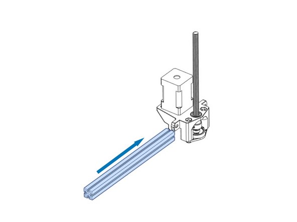
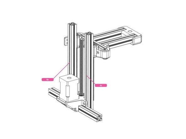
An un-drilled 200mm cross member extrusion slides into the lead screw assembly as shown.
-
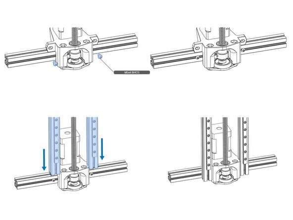
Not shown are the M3 nuts need to attach the Z rails in the second illustration.
-
The two vertical Z extrusions/rails have previously drilled hex key access holes that will be used to access the screws to tighten down the extrusions.
-
Install the two screws for attaching the Z frame, and slide the Z rails onto the screws. Center the Z frame and secure the screws. These screws may be re-tightened, later, during frame alignment.
-
-
-
Add the specified number of M3 nuts as shown.
-
Add some tape to the top of the verticals to prevent the nuts from tumbling out onto the floor, when the assembly is inverted in the next step. WARNING: The tape may stick to a nut, so using the screw/nut trapping technique mentioned in the comments below, is a better approach.
-
The bed carrier will be attached to the Z lead screw in a subsequent step.
-
-
-
Add M3 nuts as necessary for the screws in the illustration.
-
Tighten the screws.
-
Add more M3 nuts as shown, and use tape for retention.
-
-
-
Thread the lead screw into the nut block, and attach to the bed carrier with screws into pre-inserted nuts, as shown.
-
Remember, the linear rail carts have not been finally tightened, so don't worry about alignment, just yet.
-
-
-
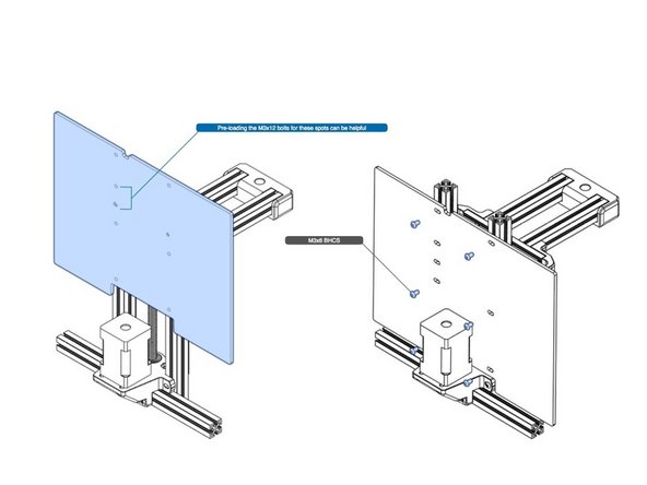
The mid panel slides in between the Z motor and the Z verticals, resting on the bottom extrusion
-
As shown in the illustration, pre-install the m3x12 screws. These will be used later to attach the Pocketwatch extruder. It is much easier to place them now into the receiving nuts, than later.
-
All holes in the panel will have screws when complete.
-
NOTE: If you use the split mid panel mod, this step can be skipped for now.
-
-
-
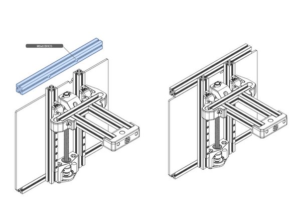
Attach an un-drilled 200mm extrusion as a top cross bar for the Z frame, using the familiar screw and slot attachment method. You will need to add M3 nuts to the extrusion for this.
-
Tighten the screws through the hex key access holes in the Z verticals.
-


Cancel: I did not complete this guide.
5 other people completed this guide.