
Difficulty
Moderate
Steps
9
Time Required

User-Contributed Guide
This guide is not managed by the site's staff.
Quiz
0
-
-
The two vertical extrusions of the Z axis are fitted with printed M2 nut guides. These guides with nuts slide into the extrusion slot.
-
IMPORTANT: Printing of the nut guides needs to be done to reduce/eliminate elephant's foot, which is a widening of the first couple of layers. Your slicer will have settings for this issue, specifically, and there are many online discussions of the problem to assist you.
-
If you cannot eliminate elephant's foot, you will need to trim the part along its length to affect a good fit. A hobby knife or de-burring tool can be used for trimming.
-
When installing the guide, carefully slide it into the extrusion's slot, nut-side down. The part is not substantial and can easily break, so go slow. Rather than push at the end of the guide, just aim to push a centimetre at a time in, this will stop it from bending or snapping. Don't forget the nuts!
-
-
-
IMPORTANT: In the illustrations that follow in this guide, any time you see a linear rail without its cart, it is assumed to be there. DO NOT remove a cart from its rail, unless you are involved in a full cleaning procedure. Wandering ball bearings in the carpet is not a good thing.
-
Leave the rail stops (sometimes red in color) that ship with the rails in place, to prevent the carts from sliding off.
-
The screws in the illustration are socket head cap screws. You may be using button head, or even flat head. That is fine. Use what you have, or whatever you feel is necessary, only be sure the heads sit below the rail top surface.
-
Use the printed rail centering guides to attach the rails. This centers the rails across the extrusion slot.
-
The whole rail is positioned along the extrusion with one end 35mm from the extrusion end.
-
IMPORTANT: When finished tape up the rail ends on the extrusion to prevent cart from sliding off.
-
-
-
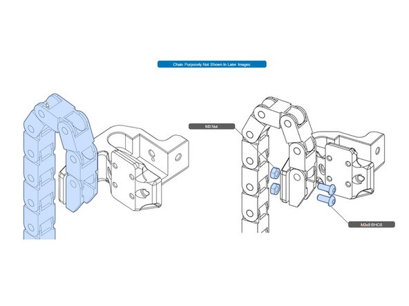
From the drag chain remove the mounting end anchor, plus one or two links. Set aside the rest of the chain.
-
Attach this short piece to to the bed carriers as shown.
-
Note: The illustration shows entire chain. You want a short piece so that the whole chain won't be flopping around as you continue the assembly.
-
-
-
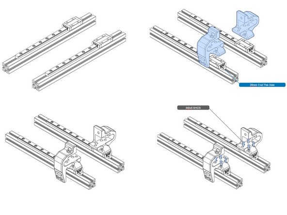
Attach bed carriers as shown. Note, the position of the 35mm spaced rail end to ensure the proper orientation of the carriers.
-
-
-
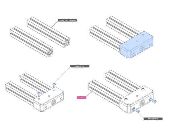
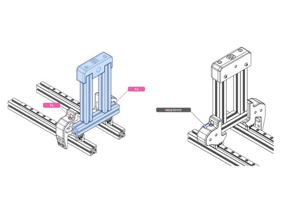
The bed carrier is assembled from three 100mm extrusions, and a printed end-cap.
-
The end-cap is fastened with four screws, two in the threaded holes at the ends of two extrusions, and two into the extrusion slots, as shown.
-
Not shown are the two M3 nuts that slide into the slots, needed for the screws.
-
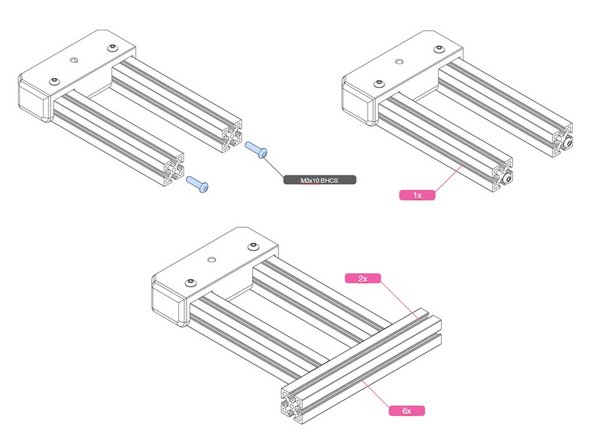
In the second illustration, the cross bar is attached with the parallel extrusion end-screws, and slotted into the cross bar. The hex driver access holes previously drilled are used to tighten up the bar.
-
REMINDER: In the illustrations, a purple flag shows the number of M3 nuts that must be inserted in the indicated slot in this step. Do so, or you will taking things apart to do it later.
-
-
-
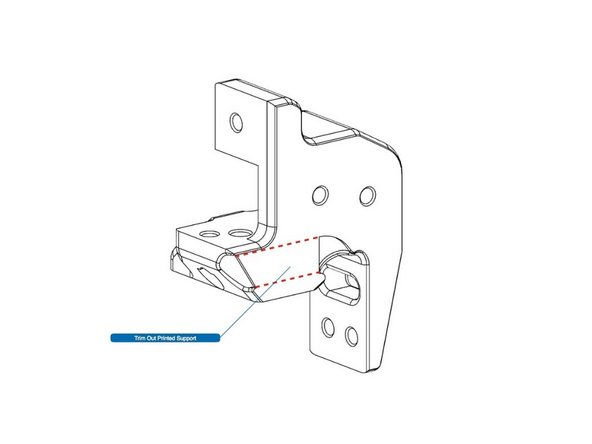
Trim out the built-in support structure in the printed part. A hobby knife and a pair of needle nose pliers will be useful.
-
-
-
NOTE: This the hard part! Mating screws to pre-inserted nuts is challenging. One technique is to use a screw to trap nuts from moving, while you put the screws in elsewhere. This is especially true of the string of six nuts in the bed frame.
-
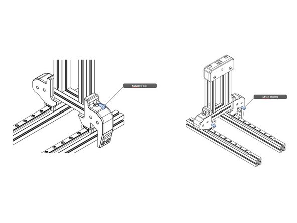
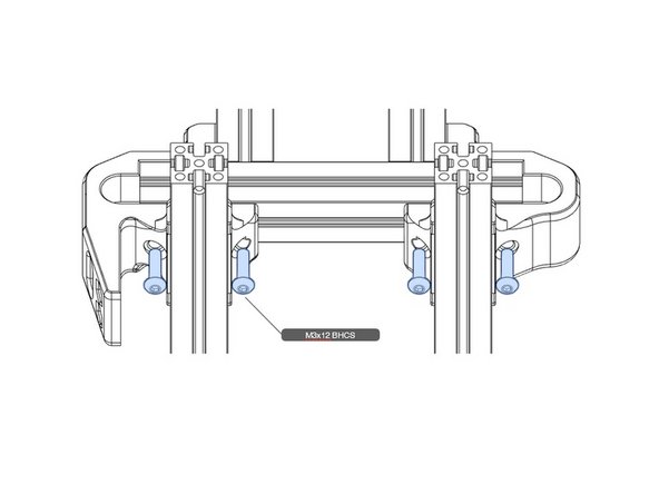
Attach the bed carrier as shown using two of the screw size indicated, one on each side.
-
If it is difficult to see where the nuts are, a useful technique is to use a flashlight to shine in the hole, and use a small hex key to push the nut along the extrusion slot, until you see the nut reflecting as it passes the screw hole. Remember this technique as it will be useful throughout this guide.
-
Insert M3 nuts, as shown.
-
-
-
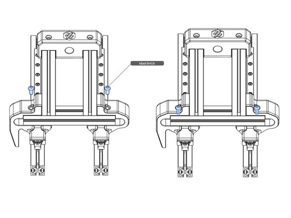
Use the three illustrations in this step to identify all fasteners of the bed frame. Make sure all are snug and tight.
-
Note: Check that there are two pre-inserted nuts remaining between the two bed rails The Z-axis will atach there.
-


Cancel: I did not complete this guide.
4 other people completed this guide.