
Difficulty
Moderate
Steps
10
Time Required
01:00:00

User-Contributed Guide
This guide is not managed by the site's staff.
Quiz
0
Tools
Parts
-
-
If you purchased untapped extrusions such as those from Misumi, you will need to tap them. MakerBeams are pre-tapped, so you can skip this discussion.
-
Foremost, use good quality taps and cutting/tapping oil. You will be cutting threads in 38 extrusion end holes ((16 200mm and 3 100mm) X 2) for the Voron 0. This will make the extrusions interchangeable. There are only a few unused taps. Best to just do them all. You may find you want to screw something into an unused tapped hole.
-
Tapping by drill driver is done by many, and recommended by none. It's a breeze right up until you break a tap. You can break taps by hand, too, but you are less likely to do so due to being able to feel the stress as you cut.
-
If possible use a ratcheting t-handle with a long neck. The ratchet aids in going slow, and the long neck makes movements in the hand less noticeable at the tap.
-
Find a good place to clamp down the extrusions to free up both hands to stabilize the tapping motion. Strapping a number of extrusions together in a block and clamping that down will make the job go faster.
-
Hand tapping involves a dip in cutting oil, a slow start, and careful attention to how the tap is cutting. Cut until a stress develops, then back up a turn, and continue on forward. The backing up will clear the chips that may be binding the tap. Continue this process until you arrive at the desired depth. Back out the tap slowly at first.
-
Note: A really good quality tap will run smooth and potentially never bind.
-
IMPORTANT: Whether hand tapping, or using a drill driver, clean the tap between each hole tapped. An artist's brush works well for this. Do not start a new hole with chips and goo on the tap.
-
-
-
The frame extrusions are held together with blind joints utilizing button head screws slid into joining extrusion slots. To tighten the screws, hex driver access holes need to be drilled in some of the extrusions. There is a printed drill guide for doing so.
-
IMPORTANT: As a precaution, make sure your linear rails are placed away from the drilling operation, or wrapped up securely to prevent metal shavings from getting into the rail cart's ball bearings, and causing havoc.
-
The illustrations show the three differently distanced holes that the guide supports. Subsequent steps show which holes are required for which extrusions.
-
In the illustrations that follow, an example extrusion is shown in two orientations (turned 90 degrees), as drilling may be done in one, or both, sides. All holes will be drilled with a 3mm drill bit.
-
IMPORTANT: The holes in the extrusions are not precision holes, but their position on the extrusion is important.
-
-
-
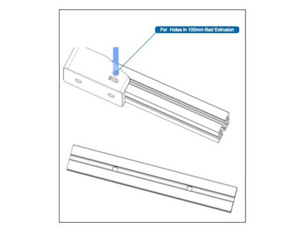
The bed mounting cross bar has a thru-hole on both ends on the same side drilled using the Bed side of the Drill Guide, as shown in the illustration.
-
-
-
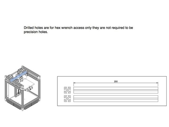
There are six 200mm extrusions that are not drilled (including X axis in previous step).
-
-
-
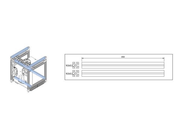
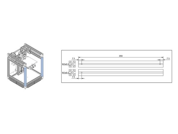
There are four 200mm rear vertical extrusions that are drilled on one side with 3mm holes 7.5mm offset from each end.
-
-
-
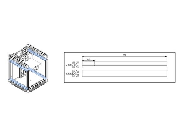
There are four 200mm front/back extrusions that are drilled on one side at one end with a 3mm hole 29.5mm offset from the end.
-
-
-
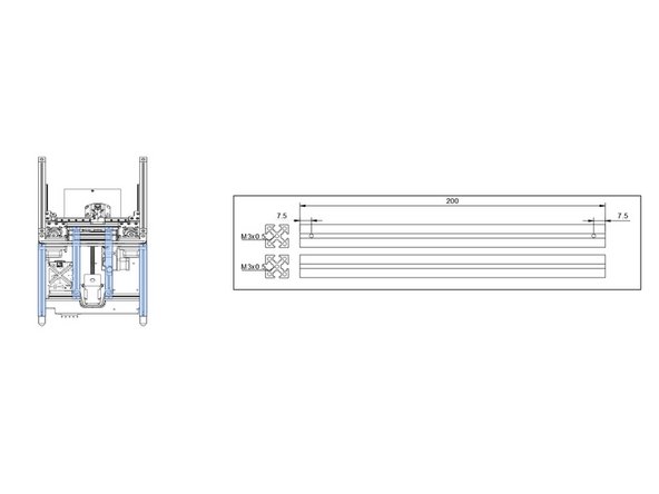
There are two 200mm front vertical extrusions that are drilled with 3mm holes at 7.5mm from each end on one side, and 7.5mm from one end of the adjacent side on one extrusion, as shown.
-
-
-
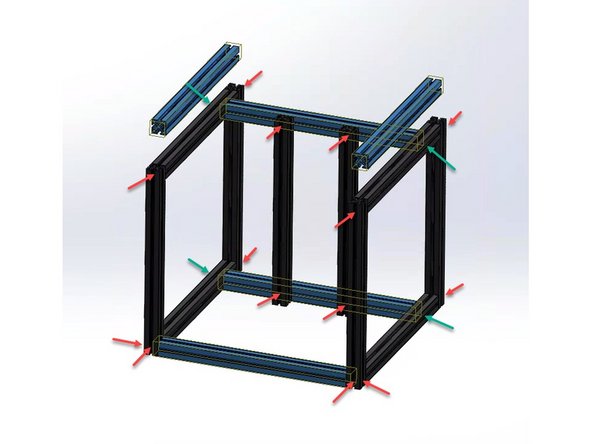
When you have completed all the hole drilling, the holes will line up on the frame as shown.
-
In the illustration, the blue extrusions require NO drilling.
-
Remember this guide/step, and refer back to it as you assemble the frame to be sure the right extrusion is used in the right place.
-


Cancel: I did not complete this guide.
4 other people completed this guide.