
Introduction
This is a guide on how I install my gantry to ensure it is square. Please note that this guide assumes you are using the Misumi extrusions from the recommended bill of materials. Any use of off-brand extrusions renders this guide ineffective.
Make sure to measure all your linear rails. You want to pick two that have the closest length measurement. Put these aside and use them for your Y extrusions. It will help get everything as close as possible.
Tools
Parts
No parts specified.
-
-
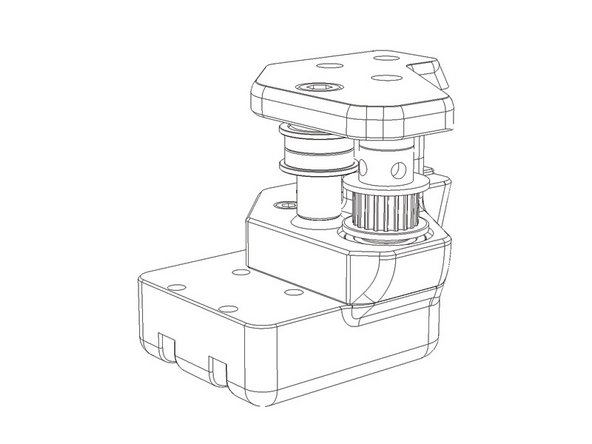
Assemble front idlers/tensioners as per the manual.
-
Ensure that there is no binding in the pulley or idler stacks.
-
Double check the assembly. It is possible to build the idlers backwards and actually install them without noticing. This will cause racking problems with the gantry if not done properly.
-
-
-
Assemble A/B drive units as per the manual.
-
Check that all grub screws are correctly seated. They should slightly bite into the drive shaft leaving a dimple.
-
Ensure there is no binding of the drive shafts or idler stacks. Adjust shims if required. Any binding at this stage will cause issues during print procedures.
-
Failure to use thread lock on grub screws can result in loosening that will cause layer shifting in print procedures.
-
Leave the accent parts that the Z belts route through off the drive units at this time. It is easier to route the belts with them completely removed.
-
Some people prefer to leave the Astrosyn dampeners off the AB drives. You may omit these if you wish.
-
-
-
Assemble X/Y joints as per the manual.
-
Ensure there is no binding of the drive shafts or idler stacks. Adjust shims if required. Any binding at this stage will cause issues during print procedures.
-
Failure to use lock nuts where instructed can cause serious problems. Please do not use regular nuts unless otherwise instructed.
-
If you haven't done so, installing the limit switches into the right X/Y joint can be helpful.
-
-
-
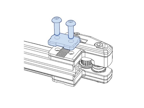
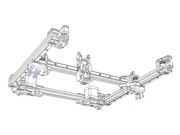
Mount the idlers on the Y axis extrusions.
-
Ensure that the front tabs are flush with the extrusion end. We are going to use the idlers to index the linear rails in later steps, so paying close attention to alignment is critical.
-
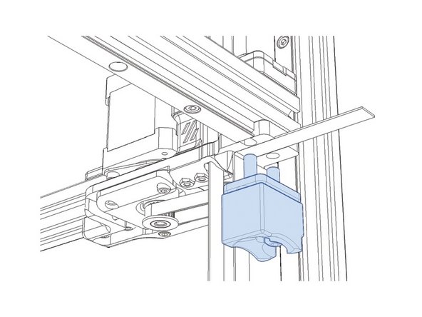
Make sure to install the Z blocks on the front idlers. Reference the manual for the correct orientation.
-
-
-
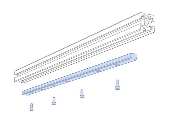
Pre-install all 3mm tnuts in the rail. Pay close attention to the orientation of the idlers in the manual.
-
A quick reference is that the M5 bolts on the front idlers should be facing up with the linear rail being installed on the bottom.
-
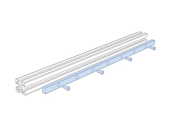
Install the linear rails onto the extrusion by tightening the m3 bolts in such a manner that the rail can still be moved back and forth.
-
Use the centered alignment tool. Any use of the offset alignment tool will cause installation problems.
-
Align the rail to the front idler. It should push flush with the printed part.
-
Tighten M3 bolts to secure the rail.
-
-
-
Pre-install all 3mm tnuts in the rail. Pay close attention to the orientation of the idlers in the manual.
-
Install the linear rails onto the extrusion by tightening the m3 bolts in such a manner that the rail can still be moved back and forth.
-
Use the centered alignment tool. Any use of the offset alignment tool will cause installation problems.
-
Do not tighten the M3 bolts on the linear rail at this time.
-
-
-
Ensure your M3 bolts on the linear rail are lose and that your guides are installed to hold it in place.
-
Install the X/Y joints as per the manual. They will pinch the linear rail into place. You may have to use a little force to ensure they are fully seated.
-
Pay special attention when bolting these parts in place. We do not want them to shift outwards just yet. The X/Y joints must stay tight on the linear rails.
-
Leave the M5 bolts that hold the X/Y joints on the extrusion. We will have to adjust this later.
-
-
-
Mount the A/B drive assemblies as per the manual.
-
Ensure that the extrusion is flush with the inside of the top mounting tab. It is the part where the M5 bolts affix the top of the drive assembly to the extrusion.
-
Verify that both sides of the A/B drive assemblies are indexed to the inside of that tab equally. If one extrusion is sticking out too far, you will have a harder time squaring the gantry.
-
Visually inspect the faces of the mounting tabs, top and bottom. Do your best to ensure that they are as square to the extrusion as possible. Depending on your printed part quality, you can use a flat object to square them up.
-
-
-
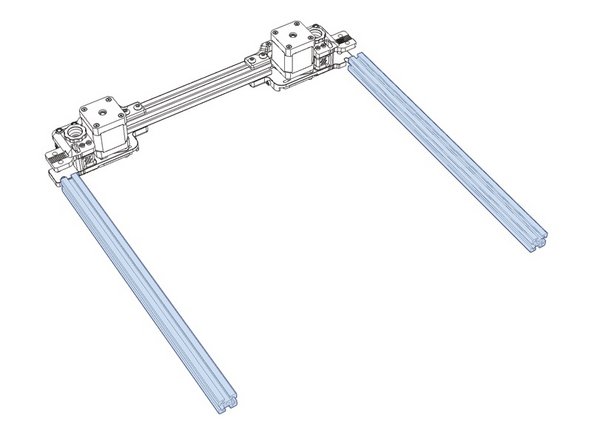
Mount the Y extrusions as per the manual. Pay special attention to the orientation of the front idlers or you'll have to re-belt your gantry if you get them mixed up.
-
Using the back of the linear rail as an index, push the AB assemblies forward until they rest flush with the rails.
-
Install all mounting bolts, including the Z blocks. Ensure you have the correct orientation by referencing the manual.
-
If you are using a hall effect end stop, make sure you have the correct Z block for that application.
-
This procedure is attempting to use the front idlers as the first index. Then use the linear rails as the next index. And finally install the A/B assemblies so that the mounting is as square as possible.
-
With slightly lose bolts on each assembly. use a framing square between the stepper motor and the Y extrusions to ensure squareness of the mounting. Tighten the top bolts to secure. Recheck squareness and then tighten bottom bolts.
-
-
-
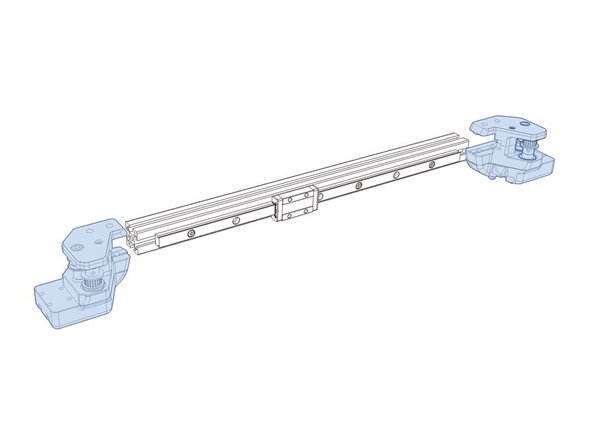
Mount the X beam assembly as per the manual.
-
Ensure that the M5 bolts on the top and the bottom of the X/Y joints are slightly loose.
-
Various thread lock compounds are known to break down ABS and cause significant damage. It is recommended that you add a small amount directly to the threaded holes of the carriage, rather than place it on the bolt.
-
-
-
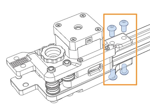
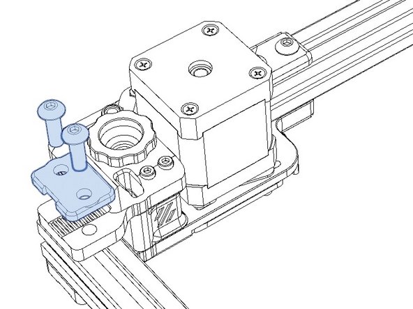
Loosen the 4 bolts on the back of both A/B assemblies and re-tighten.
-
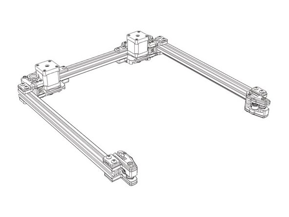
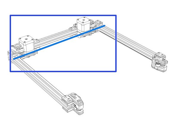
Slide the X beam to the rear of the gantry.
-
Measure the outer diameter of the gantry at the back. It should measure 409mm for a 250 build, 459mm for a 300 build and 509mm for a 350 build. Adjust the A/B mounts on the rear extrusion until this width is achieved.
-
The width here is critical. Having one joint offset from the linear rail will cause print quality issues. Snap them in as far as they will go.
-
With the X/Y joints bolted in place, tighten the M3 bolts on the linear rail ensuring the center guides have not slipped off.
-
Tighten the M5 bolts on the X/Y joints.
-
-
-
Loosen the outer A/B assembly bolts on the top and bottom slightly.
-
Slide the X beam all the way forward so it rests on the front idlers.
-
Ensure that the AB drive units are resting on the linear rail on both sides. It should be flush against it with no gaps.
-
Tighten the outer A/B bolts on the top and bottom.
-
-
-
With the gantry assembled, slide the X beam back and forth and check for any spots that bind. It should run the full length of the gantry smoothly.
-
This should be done without AB belts. We left them off previously so we could check for binding at this step.
-
If there is any binding, you will have to go back and re-check steps.
-
Install AB closed loop belts as per manual.
-
-
-
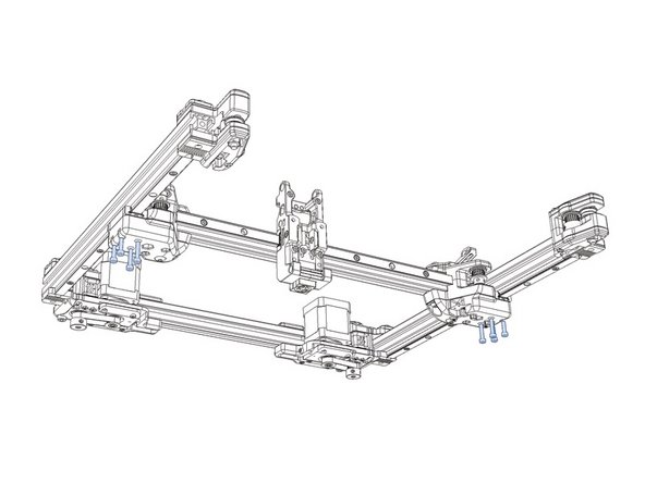
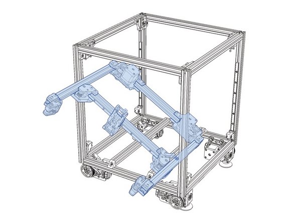
Your basic assembly of the gantry is complete. Now you can move on to installing the gantry.
-


Cancel: I did not complete this guide.
One other person completed this guide.
