Difficulty
Moderate
Steps
14
Time Required
06:00:00 - 08:00:00
- Assembly 14 steps

In Progress
This guide is currently being written. Reload periodically to see the latest changes.

User-Contributed Guide
This guide is not managed by the site's staff.
Quiz
0
Introduction
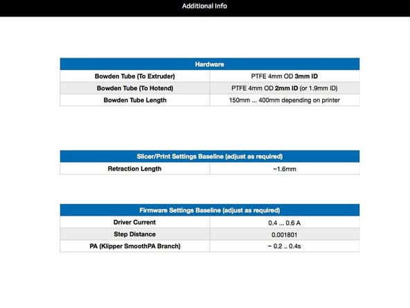
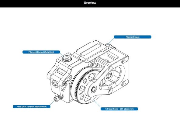
The Voron Jetpack filament feeder is designed to be lightweight, compact, and to minimize its feeder to hotend Bowden tube length, when installed on the Voron 2 series of 3D printers. The shortened Bowden tube makes retraction tuning easier and more accurate as there is less room for play in the filament path. Care has been taken to minimize the part count, and to use readily available parts from reliable suppliers.
The material herein is an expanded version the Voron Assembly Manual developed by the Voron Development Team. All diagrams and tables were created by that team during development.
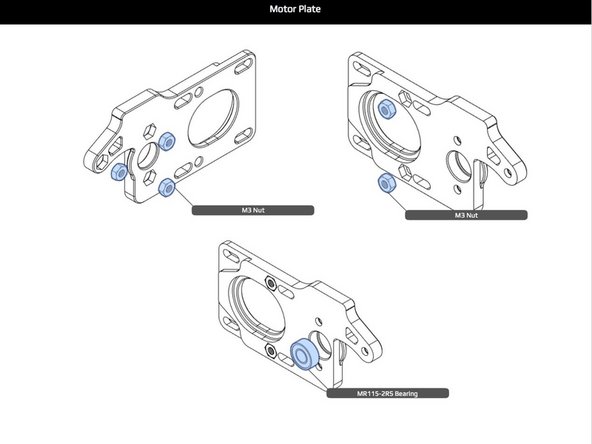
-
-
Press fit the nuts by hand, or lightly with parallel pliers. Ensure that there are no stress marks around the nuts. If stress marks appear, re-print the part for greater dimensional accuracy.
-
Press fit the bearing by hand, or lightly with a press. If it goes in too tight, re-print the part for dimensional accuracy.
-
Aside: Throughout this manual where parts are pressed into other parts the use of a press, while not officially recommended, can help, only if lightly used. Any sign of stress marks at press points should be your cue to reprint the part for better dimensional accuracy, and try again.
-
-
-
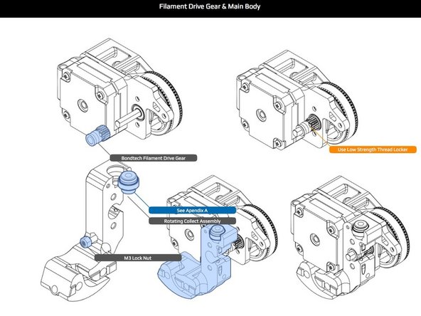
Use thread locker (see Sourcing Guide) on all grub screws. It is easiest to apply thread locker to the screws and into the part before installation on a shaft.
-
The 16T pulley when finally adjusted must have one of its grub screws seated properly on the flat of the shaft. Tighten the screw gently until it hits the flat, while tightening a little bit further, rock the pulley back and forth to find the exact alignment of the grub screw to the flat. Visually inspect. Finish with a good crank on the screw.
-
Attach the stepper motor with wires positioned downward, as they will be run along a groove in the main body to route the wires to the X cable chain.
-
Attach all parts as shown. The lateral position of the 5x45 shaft w/flat should be in line with the back of the stepper motor, specifically with the flat area where the screw heads seat on the motor's backplate.
-
The printed pulley spacer may be snug on shaft, but should spin freely in the recess when against the bearing. An alternative of 7mm metal shims may be used in place of the printed spacer.
-
-
-
The 16T pulley flange can be removed with a bottle cap remover. Press fit the pulley as shown being careful with alignment, and ensure that it is fully seated to the 62T pulley hub.
-
The grub screws will be tight to start, but once started should be screwed in until the heads are beneath the hub's surface. Same instructions as before apply to grub screw installation for securing the 62T pulley to shaft with flat. Note how the two pulley's align in the illustration.
-
Install the belt.
-
-
-
Press fit the bearing in a similar fashion as described previously. After the end plate[?] has been installed, check shaft positioning, and adjust as necessary. This may require re-positioning of previously installed parts.
-
At this point, ensure that the bearing that abuts the printed spacer is fully seated and flush in its recess, as this is crucial for the filament drive gear to be properly aligned. That bearing was installed in previous assembly step.
-
Install the drive belt, if not previous done so. Then, install the yoke/back plate and filament input guide as shown.
-
Aside: At this point, the middle shaft bearing, the spacer, the 62T hub pulley assembly, and the back plate with its bearing are a single bound unit with no play, and that crucial middle bearing is fully seated in its recess. If on inspection this is not so, then disassemble and figure out what is not aligned correctly.
-
If this is not done right the filament drive gear will not be aligned with the filament path. There will be less than a millimeter of adjustment space at the filament drive gear, so this alignment must be right
-
-
-
Install Bondtech filament drive gear (the one with the grub screw) and in a similar fashion as the shaft pulleys previously installed. The gear should be snug to bearing as shown.
-
Hand press fit M3 lock nut, as shown.
-
Prepare collet according to instructions in Appendix A. Since the free spinning of the collet in the bearing can be inhibited by its rubber seal, do not use the seal. The collet assembly should be hand pressed into the main body as shown.
-
IMPORTANT: Before bolting up the main body in the Jetpack assembly in the next step, there are three bores that need to be checked for sizing. If you don't do this now, trying to fix these bores after assembly can very difficult.
-
Using a piece of filament, ensure that it can be inserted and does not bind in the two bores (holes) and that it aligns the filament to the filament drive gear.
-
The third bore that needs to be checked is the output receiving bore for the Bowden tube. Insert a piece of the tube you will be using for this connection, and ensure that it spins freely in the bore, or it will not do so later when installing the Jetpack on the printer.
-
-
-
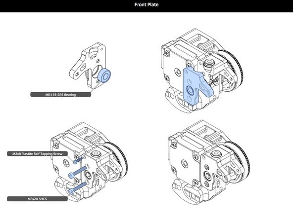
As before, the bearing should be hand pressed into the end plate as shown. Bolt the plate through the main body and into opposite bearing plate where there are receiving nuts. Add one self tapping screw as shown making sure it is tight, but avoiding stripping the plastic in which it is screwed.
-
The M3x20 screws used to fasten the end plate are just long enough. When screwing them in, ensure that they properly catch the threads, and do not push out the nuts. M3x22 screws can be used as an alternate, and will fully go through the nuts.
-
Check the alignment of the Bondtech drive gear. There is a slight bit of room for adjustment. Loosen the grub screw, and re-align, if possible. You may need to re-apply thread locker. If alignment is not possible, re-doing previous steps may be necessary.
-
-
-
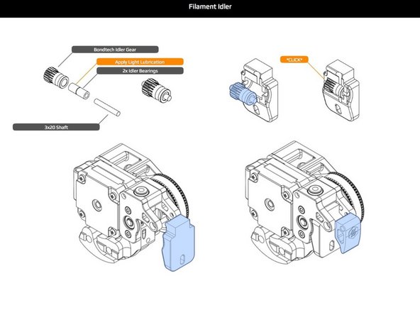
Prepare the Bondtech idler gear for installation. Ensure that your Bondtech kit is supplied with an M3 20mm shaft. This shaft does not need a flat. The idler has two needle bearings that must be lubricated with a tiny amount of lithium grease.
-
Use of a toothpick helps distribute the grease evenly. Be careful not to contaminate the bearing with grit or dirt from the work bench. Install bearings on m3 shaft and wipe away the excess grease. Install the assembled idler gear into its plastic holder as shown, listening, or feeling, for a click to know it is in place.
-
-
-
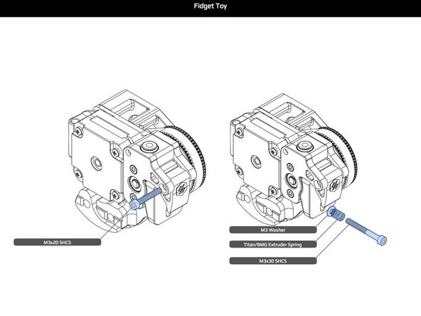
Install the idler holder and latch as shown along with the idler tensioning spring. If your Bondtech kit did not include a spring, check the Sourcing Guide for alternatives.
-
-
-
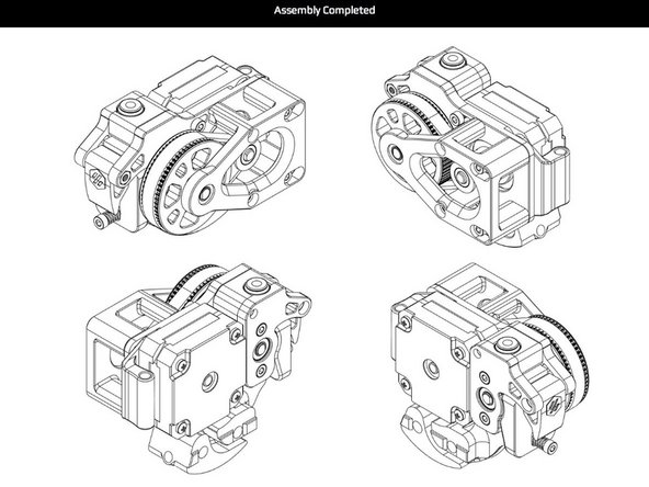
The Jetpack is now complete as shown on this page. There should be no leftover parts, other than intended substitutions. Good job!
-
-
-
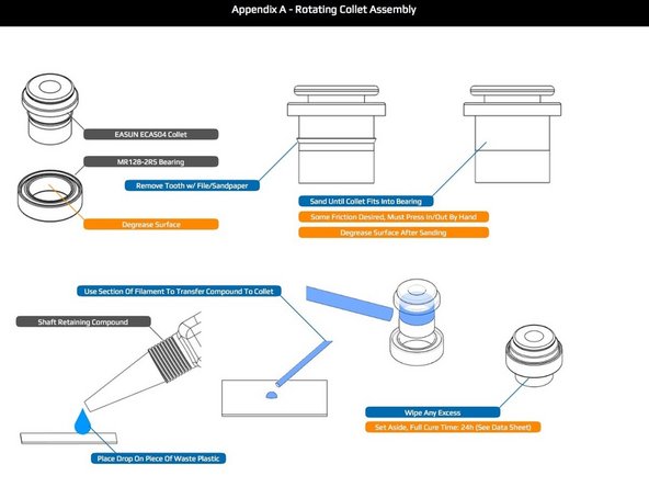
The collet may be prepared for assembly in number of ways. The main issue is removing the flanged "tooth" on the outside of the collet. Hand sanding, or filing is simple, requiring minimal tools.
-
Use of a flat head screw and nut to chuck the collet into a drill, and running it across a file is another popular method. In any case, care must be taken not to overdo the abrasion. The fit in the bearing should be quite snug, but hand insertable.
-
The collet is fitted into its bearing with shaft retaining compound. To properly apply this compound, the surfaces must be clean and oil free. A small Q-Tip like swab may help. Wipe with isopropyl alcohol being careful not to get any on the bearing's seal.
-
When applying the shaft retaining compound as shown, again, be careful not to get any of the liquid on the bearing's seal. If you do, ensure that you wipe it off thoroughly.
-
After assembly, set aside for at least a day before use. Longer is better, but not neccessary.
-


![Press fit the bearing in a similar fashion as described previously. After the end plate[?] has been installed, check shaft positioning, and adjust as necessary. This may require re-positioning of previously installed parts.](https://d3t0tbmlie281e.cloudfront.net/igi/voron/QRiPPZFDPJLHQNkc.medium)